

PIPING ENGINEERING
At Technitas Pvt. Ltd., we ensure that the Piping design phase involves close collaboration between piping designers, process engineers, stress analysts, and other disciplines to ensure that the piping systems are designed in compliance with applicable codes and standards, meeting the project requirements and specifications while considering factors such as accessibility, maintainability, and cost-effectiveness. Typical set of piping engineering deliverables include :-
➣ Plot Plan- Detailed layout drawing would depict the entire plant area, including the arrangement of major equipment, buildings, access roads, and other facilities. It would serve as the basis for piping routing and helps identify potential clashes or interferences during the piping design phase.
➣ Piping Line List / Critical Line List - The piping line list is a document that lists all the individual piping lines in the plant, along with their unique line numbers, service descriptions, and other relevant information. A critical line list identifies the piping lines that are critical to the process or safety, requiring additional attention and specific design considerations.
➣ Piping Material Specifications (PMS) - The PMS is a document that specifies the materials of construction for piping components, such as pipes, fittings, valves, and flanges. It considers factors like process conditions, fluid properties, and corrosion resistance requirements. The PMS ensures consistency in material selection and compliance with relevant codes and standards.
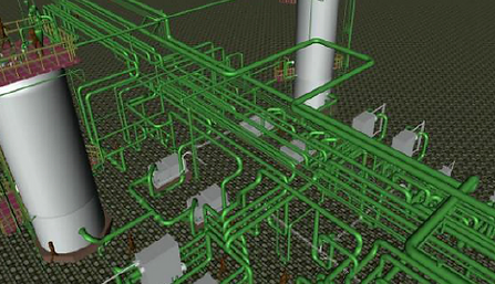
➣ 3-D Modeling of Plant Piping - Advanced 3D modeling software is used to create a comprehensive 3D model of the plant piping systems. The 3D model helps visualize the piping layout, identify potential clashes or interferences, and supports the generation of isometric drawings and other fabrication documents.
➣ Piping Layout Drawing - The piping layout drawing is a detailed 2D or 3D representation of the piping systems, showing the actual routing, elevations, and connections to equipment. It includes information such as pipe sizes, materials, and locations of valves, fittings, and other components. The piping layout drawing is used for construction, fabrication, and installation purposes.
➣ Piping Material Take-Off - The piping material take-off is a detailed list of all the piping components required for the project, including pipes, fittings, valves, flanges, and gaskets. It is generated based on the piping layout drawings and is used for procurement and material planning purposes.
➣ Piping Isometric Drawings - Piping isometric drawings are 3D representations of individual piping lines or spools, showing accurate dimensions, orientations, and the locations of all components (pipes, fittings, valves, etc.).These drawings are used for fabrication purposes and serve as a reference for welders and pipefitters during installation.
➣ Valve List – list of all the valves used in the piping systems, along with their unique valve numbers, types, sizes, materials, and other relevant information. It is used for procurement, installation, and maintenance purposes.
➣ Valve Datasheets - Valve datasheets are comprehensive documents that provide detailed specifications for each valve, including dimensions, pressure and temperature ratings, materials of construction, and other technical information. These datasheets ensure that the correct valves are procured and installed in the piping systems.
➣ Piping Support Schedule - The piping support schedule document would include a list of all the pipe supports required for the piping systems, including their types, locations, and loading information. It is used for the design and fabrication of pipe supports and ensures adequate support for the piping systems.
➣ Pipe Support Drawings – Detail fabrication drawings that show the design and dimensions of various pipe support types, such as guides, anchors, shoes, and spring hangers. These drawings are used for the fabrication and installation of pipe supports, ensuring proper support and allowing for thermal expansion and contraction of the piping systems.