

ELECTRICAL AND INSTRUMENTATION


Technitas Pvt. Ltd. specialize in the design and detail engineering of Modular process skids wherein most cases our E&I (Electrical and instrumentation) scope is typically inclusive up-to the battery limit of the modular process skid, in these scenarios the set of drawings, diagrams, and associated documents essential for the proper design of instrumentation and electrical systems include:-
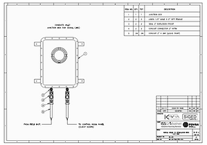
➣ Junction box detailed drawings which would typically include the complete design and fabrication details for the junction boxes used in the instrumentation and electrical systems. These drawings include dimensions, materials of construction, entry/exit points for cables, and any specific requirements or certifications needed (e.g., hazardous area classifications). The Bill of Quantities (BOQ) lists all the components required for the junction boxes, such as enclosures, terminals, glands, and accessories, along with their quantities and specifications.
➣ Junction Box Wiring Diagram: Junction box wiring diagrams illustrate the interconnections between the incoming and outgoing cables within each junction box. These diagrams show the cable terminations, terminal numbers, and any internal wiring required. They serve as a reference for the installation and termination of cables within the junction boxes.
➣ Instrument Cable Schedule with BOQ: The instrument cable schedule is a document that lists all the instrument cables used in the project, including their unique cable numbers, cable types, lengths, and termination points. The BOQ associated with the cable schedule provides the quantities and specifications for each type of cable required, facilitating procurement and material planning.
➣ Instrument and Junction Box Location Drawing: Our drawing would typically include the physical locations of all the instruments and junction boxes within the plant or facility. It helps in visualizing the cable routing and identifying potential obstacles or constraints during installation. The drawing may also include details like cable tray routes, equipment locations, and other relevant information.
➣ Instrument Hook-up Diagram with BOQ: The instrument hook-up diagram would illustrate the connection between instruments, junction boxes, and control systems or panels. It will typically depict the cable routings, cable numbers, and termination points for each instrument signal or loop. The associated BOQ lists all the required components, such as cables, cable glands, terminals, and any specialized hardware or accessories.
➣ Instrument Loop Wiring Diagram: Instrument loop wiring diagrams provide detailed wiring information for each instrument loop or signal circuit. They show the interconnections between instruments, junction boxes, marshalling cabinets, and control systems, including cable numbers and terminal designations. These diagrams are essential for the installation, termination, and troubleshooting of instrument loops.
➣ Instrument Pneumatic Connection Diagram with BOQ: For pneumatic instrumentation systems, the pneumatic connection diagram depicts the routing and connections of pneumatic tubing or piping between instruments, control valves, and air supply systems. It includes details like tubing sizes, materials, and any specialized fittings or components required. The associated BOQ lists the quantities and specifications for the pneumatic tubing, fittings, and related components.
➣ Instrument Logic Diagram: Instrument logic diagrams illustrate the logical relationships and interactions between various instruments and control systems. They show the signal flow, interlocks, permissive conditions, and control logic using standardized symbols and notations. These diagrams are crucial for understanding the overall control philosophy and troubleshooting control system issues.
➣ Instrument Cable Tray Layout with BOQ: The instrument cable tray layout drawing shows the routing and arrangement of cable trays used for instrument and electrical cables within the plant or facility. It includes details like cable tray sizes, elevations, and any necessary supports or fittings. The associated BOQ provides the quantities and specifications for the cable trays, supports, fittings, and any other required components.
At Technitas Pvt. Ltd. we firmly believe that Automation and Controls are critical components in modern industrial facilities, enabling efficient process monitoring, control, and optimization. Here's an overview of various aspects of engineering services offered by us related to electrical and instrumentation automation and controls.
Electrical and instrumentation automation and controls require a multidisciplinary approach, involving expertise in electrical engineering, instrumentation, control systems, and process engineering. Effective design, implementation, and integration of these systems are crucial for achieving safe, reliable, and efficient operation of industrial facilities.